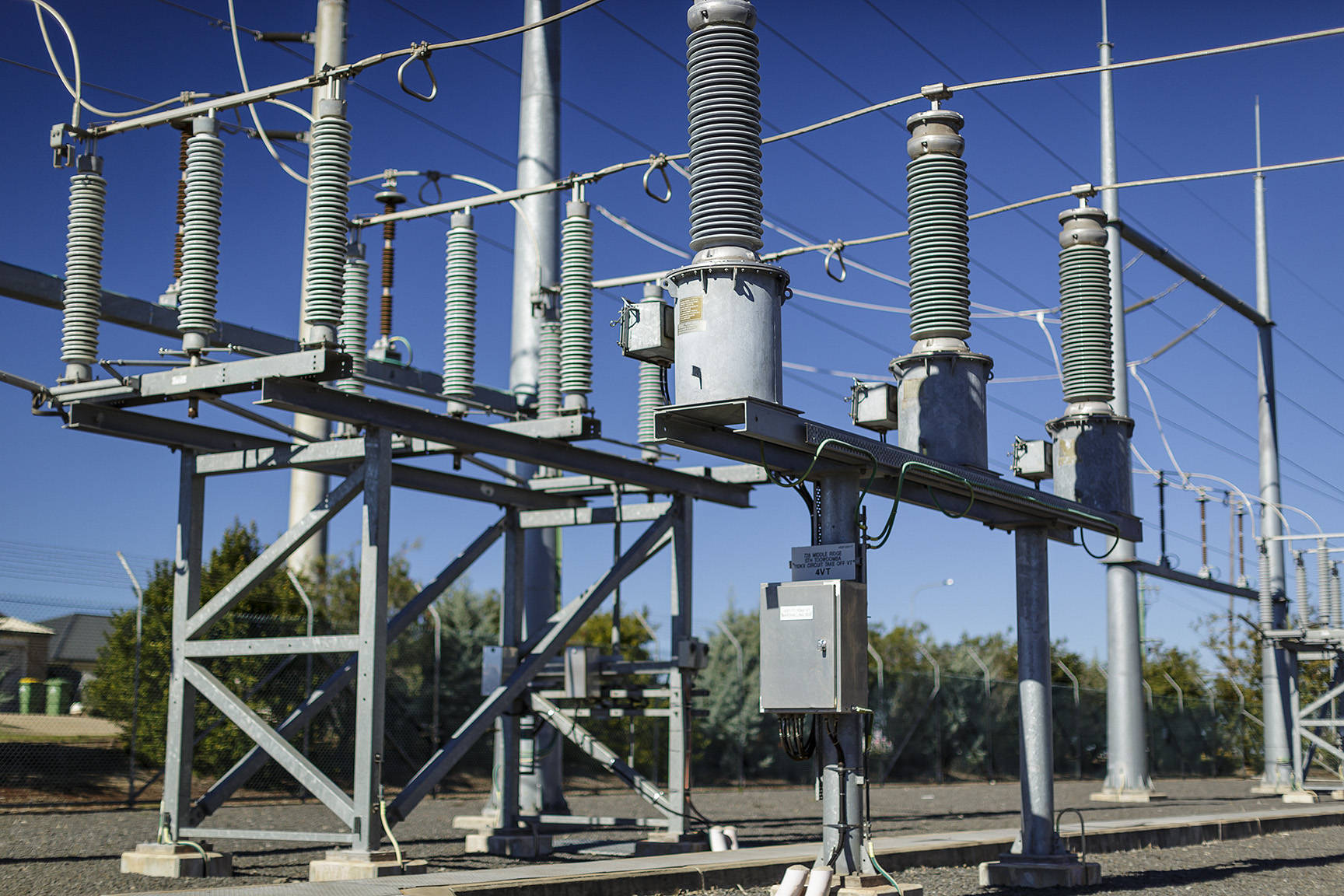
Fault levels
Fault levels on our network are affected by both internal and external factors, such as the Transmission Network Service Provider’s network, generators and customer connections.
Internal factors
Fault level increases due to augmentation works within our network are managed by putting policies in place to ensure that the works will maintain short circuit fault levels within allowable limits.
External factors
Fault level increases due to external factors are monitored by annual fault level reporting, which estimate the prospective short circuit fault levels at each substation. The results are then compared to the maximum allowable short circuit fault level rating of the switchgear, plant and lines to identify if plant is operated within fault level ratings.
We obtain upstream fault level information from Transmission Network Service Providers annually and changes throughout the year are communicated through joint planning activities.
New connections of distributed generation and embedded generations which increases fault levels are individually assessed to ensure limits are not infringed. Known embedded generators are added to our simulation models so that the impacts of these generators on the system fault levels are determined.
High voltage fault level limits
The table below lists design fault level limits that apply at our installations. It's recommended this table is used when designing your network.
| Voltage level (kV) | Short circuit level (MVA) | Short circuit level (kA) |
|---|---|---|
| 132kV | 5,715/7,200 MVA | 25/31.5 kA |
| 110kV | 4,763/6,000 MVA | 25/31.5 kA |
| 33kV | 749/1,428 MVA | 13.1/25 kA |
| 11kV | 250 MVA | 13.1 kA |
Low voltage network fault levels
The maximum three-phase fault currents that can be expected on the Low Voltage (LV) terminals of a distribution transformer are set out in the table below.
| Network rating (kVA) | Transformer type | Transformer nominal impedance (%) | Maximum LV three-phase fault current (kA) |
|---|---|---|---|
| 25 | Pole mount | 3.30% | 1.1 |
| 63 | Pole mount | 4.00% | 2.3 |
| 100 | Pole mount | 4.00% | 3.7 |
| 200 | Pole mount | 4.00% | 7.4 |
| 315 | Pole mount and padmount | 4.00% | 11.7 |
| 500 | Pole mount and padmount | 4.00% | 18.5 |
| 750 | Pole mount | 5.00% | 22.2 |
| 1000 | Pole mount | 5.00% | 29.6 |
| 1500 | Pole mount | 6.25% | 35.6 |
The fault currents correspond to a worst-case transformer impedance of 90% of nominal impedance, as transformer standards allow for a ±10% tolerance on nominal impedance. These values also assume an infinite HV bus is applied at the transformer at 1.0p.u. voltage.
The pole transformer size is written on the transformer tank (for newer transformers) and is visible from the ground. The padmount transformer size is also written on the tank (for newer transformers).
Standard distribution transformer LV fusing information can be found within our Overhead Construction Manual and our Underground Construction Manual. Note that some older transformers may have different LV fuse sizes installed as compared to the current standard fuse size, and some padmount transformers may have an LV circuit breaker installed.
Requesting detailed information
If you with to obtain more detailed fault level information, there are two ways you can do this:
Option 1 - Locate the information in available data
Determine the zone substation you are supplied from (available from your electricity retailer) and then locate the relevant substation and associated fault level within the Annual Fault Study Summary Report (XLSX 209.8 kb).
Option 2 - Complete our online enquiry forms
Please note there is a fee for this service. Its a two step process as follows:
- Complete the Fault Level Enquiry form.
- Complete the Fault Level Enquiry form and you'll receive an email with an attached text (.txt) file which is a summary of your competed form. Save this text file and attach it to your Asset Relocation Enquiry (see step 2).
- Submit an Asset Relocation Enquiry.
- Submit an Asset Relocation Enquiry via the Electrical Partners Portal attaching your saved Fault Level Enquiry form summary text (.txt) file.
Rule of thumb for Brisbane Urban substations at 11kv include:
- Approximately 8-10kA 3 ph. fault level at the start of the feeder
- Approximately 3-5kA 3 ph. fault level at the end of the feeder
- Approximately 2kA ph.-E fault level at the start of the feeder
- Approximately 1.5kA ph.-E fault level at the end of the feeder
- Typical OH 11kV feeder conductor is 7/4.75AAC
- Typical UG 11kV feeder conductor is 240mm Al

